During power profiling, I discovered a surprising difference in current consumption between two LoRa devices: the generic node and a custom board (NUCLEO-L073RZ paired with the SX1261).
The custom board uses the NUCLEO-L073RZ, which features the STM32L0(Cortex-M0 processor). I have connected this to the SX1261MB2xAS Mbed shield containing the SX1261 LoRa chip. As far as I know, the SX1261 is known for its low power consumption, compared to the SX127x and SX1262.For this setup, I’m using the SWL2001,SWL2001.
The generic node, on the other hand, uses the STM32WL5CC, which includes both Cortex-M0 and M4 cores, along with an integrated SX126x LoRa module. I’m using the sensors_lorawan example from the corresponding GitHub repository.
Both devices are configured with:
Spreading Factor: SF12
TX Power: 14 dBm
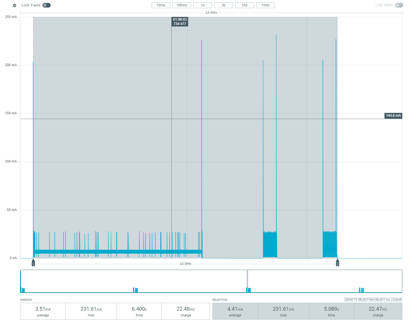
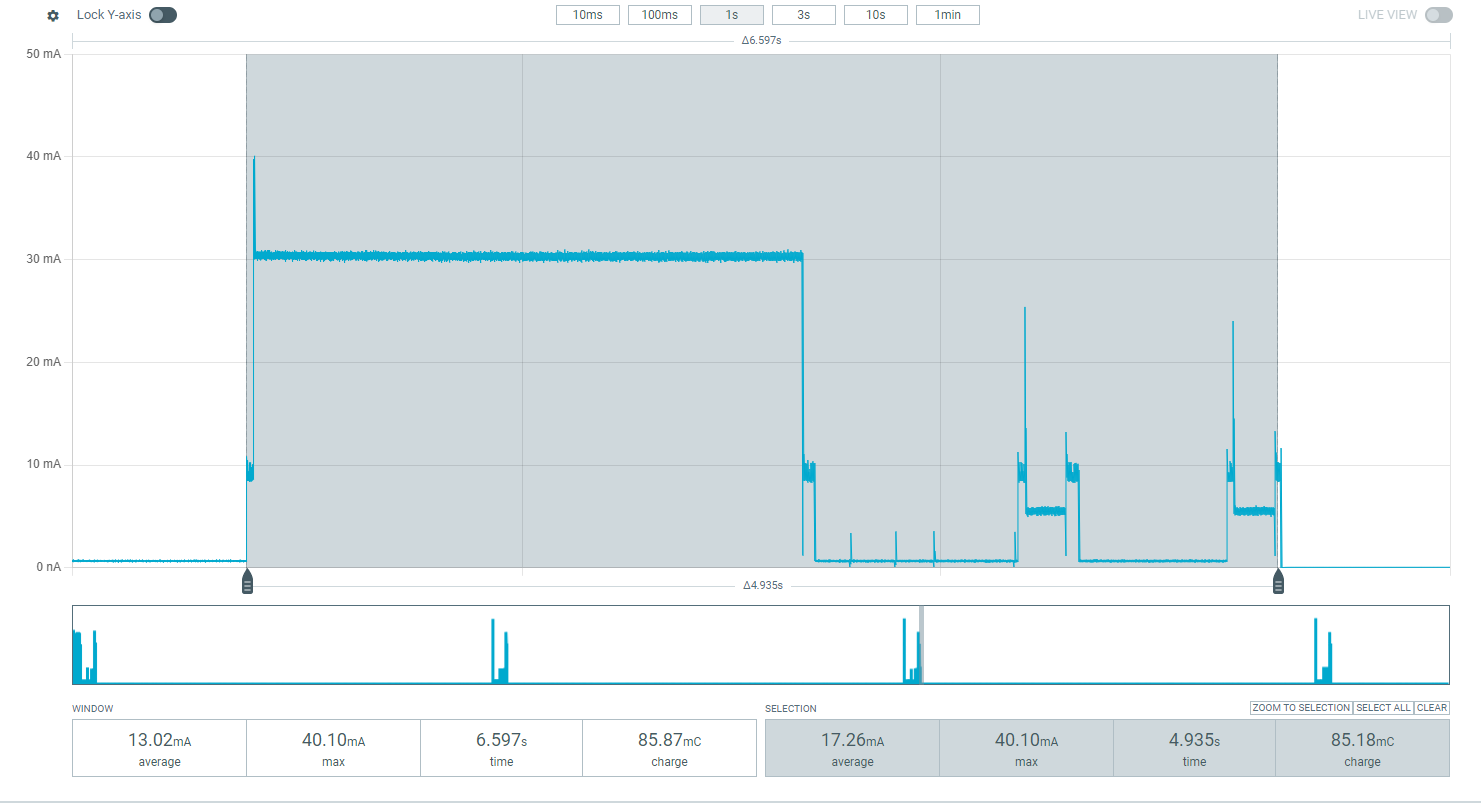
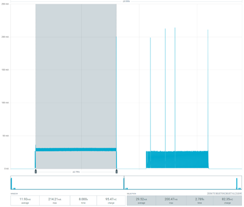
However, the power consumption results are drastically different. Both images show the expected TX and RX1/RX2 windows
Custom board (NUCLEO-L073RZ + SX1262MB2xAS): Consumes on average 17 mA.
Generic node: has peaks at 25 mA, but overall averages around 4 mA.
Do you know why there is such a large discrepancy? Could it be due to differences in hardware initialisation or firmware configuration, or could there be an issue with the radio driver?
This is like comparing the fuel consumption of a generic mid-range SUV vs a customised high-end two seater coupe.
The power consumption is a factor of so many elements around the Blinkenlights, the voltage regulators, interfaces for all sorts of things on the dev boards that aren’t required in real life so aren’t on the Generic Node etc etc.
None of these - how we setup chips & write the firmware has a considerable amount of impact on power use, but in this case, as you are using the same firmware, it’s all down to the excellent design that @cndrxn produced. However, do NOT use the same voltage reg unless you are using PnP as it’s BGA and almost broke his balls trying to place it in the online-build-a-thon.
I also very much wonder whether the measured power from the GN is OK, since the transmission appears to consume roughly 5mA, which is definitely not enough for 14dBm. The custom board looks spot-on in that regard.
Are you really measuring the power consumption of the device as a whole? My guess is that you have just measured the MCU on the GN. Its power rails are very interesting and I suspect that the radio is separated from the power lines that you measured.
As a side note: the SX1262MB2xAS appears to have an SX1262 on board as opposed to the SX1261MB2xAS. I assume you use the latter?
Also, make sure any debuggers are disabled and physically disconnected, as these can draw a significant current. Same for (uart) communication with a device that has slightly different levels, this can draw or supply power as well.
You didn’t tell us how you’re powering your DUTs.
GN uses a buck-boost converter which are inherently highly efficient, but the Nucleo boards use linear regulators.
Looking at the screen shots a bit harder, the GN power consumption is hard to read. The Tx phase seems to have a lot of artifacts (spikes) and is either transmitting at the lowest possible power level which it isn’t per the (somewhat hard to read) logs or is just plain wrong.
It’s actually peaking ten times higher! I have no idea how to inspire the 231mA spikes we see at the end of the Tx and wrapped around the Rx phases.
The Nucleo combo power trace looks as I’d expect but I’ve not run that combo with SWL2001, only using an L476 board, which is close enough.
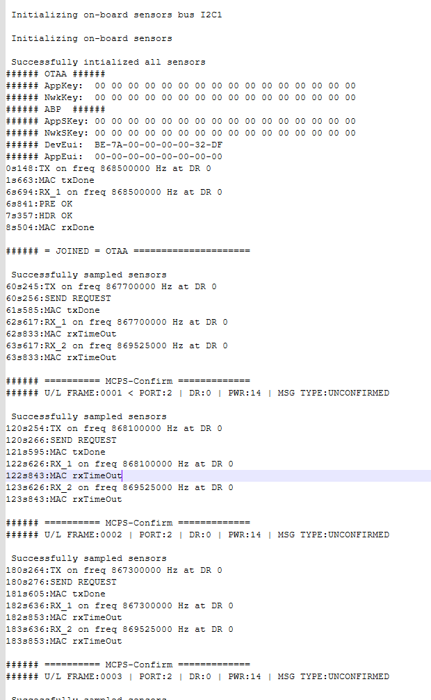
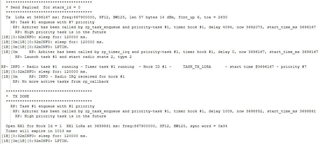
As for the serial output, please always post text as text - easier to read / copy & paste / parse as required.
There is something up with that GN trace, as Orkhan says, can you tell us how you have this powered and are you aware that the board runs at 2.8V?
I’m using the Power Profiler Kit 2 (PPK2) from Nordic, which can simultaneously measure power consumption and supply power to a device. I connected it as shown here: PPK2 docu.
I connected the VIN of the GN board to the VOUT of the PPK2. I also connected the GNDs of both the PPK2 and the GN board together. For monitoring output, I connected the TxD pin of the GN board to my UART-to-USB converter, which allows me to view data in a terminal. I also did an check, if it outputs the power I configured it PPK2 - It does. The output is configured at 3.3V.
Yes, I am aware of it. For the Nucleo boards, I am measuring the current consumption after LDO and with the GN before the DC/DC converter.
I tested both configurations. With the debugger enabled, the GN draws 2 mA in low power mode. When the debugger is disabled, the PPK2 measures a current consumption of 0.55 µA. However, according to the datasheet, the expected current in STOP2 mode with RTC enabled and VDD set to 3 V is 1.07 µA. This discrepancy may be due to PPK2 inaccuracy. The UART is automatically disabled when not needed in the example.
Thanks! That was a typo. I have corrected it — I am using the SX1261MB2xAS board.
I am measuring the current before the DC/DC converter, with the LoRa module integrated within the MCU. Therefore, it is unlikely that there is another power rail that I am missing. I also removed the external debugger, but this had no effect on the measurement results. Am I missing something?
I can see in my gateway that the data is coming from the GN. As can be seen in the images I posted, the current peaks at 25 mA, which aligns with the TX power specifications (14 dBm at 3.3 V). After the peak, the current oscillates. Initially, I thought this might be due to intelligent radio scheduling to optimize power consumption.
I am also having trouble identifying the current consumption of the TX and the MCU.
I also checked the software stack to verify whether the SetTXParam message was being sent to the LoRa module with the right value. Initially, the transmit power was set to 0 dBm, so I was concerned that my configuration changes had not been applied. However, after debugging it, I confirmed that the transmit power had been updated to 14 dBm as intended.
I do not consider peaks of over 200 mA to be part of the transmission. I thought they might be required for system start-up, though. However, as you mentioned, they could play a role.
Okay, good. I will do that in future. I can post it again as text if needed.
I am supply at VIN, therefore the converte is taking this for me. ( As long I provide the voltage in the range specified.)
I’ve identified the reason for the difference in energy consumption. It turns out that the Generic node was configured differently than the Nucleo board.
According to section 2.4.3 of the LoRaWAN Regional Parameters specification, the constant TXPower_0 does not correspond to 0 dB; instead, it represents the maximum Equivalent Isotropically Radiated Power (EIRP). I had previously set the configuration to TXPower_14, which is not defined in the standard. Consequently, the library probably defaulted to a lower power level, likely 0 dB.
After reverting the configuration to TXPower_0, the average transmit current increased to 29 mA—matching the value observed on the Nucleo board using the SX1262.
However, I still observe current peaks (around 200 mA) during LoRa transmission and reception. Could you help me understand why this is happening?